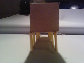
Very exciting I must say, laser cutting for the first time. After finishing my confusing file on illustrator, and sending it to the laser cutter I started to piece together the pieces. Unfortunately with football interupting most of my model making process... I did not finish the model to what I wanted it to look like. I wanted to create small seating areas for under the roofing, and create pergola like structures that extended off the 3 peaking rectangles... But anyway, here is the making, and final model.
I thought to be honest, this model couldve finished a lot better, as I did not manage to find thin enough dowelling lying around, and the seating and pergolas wouldve been a nice added detail. The small facade underneath the roofing sepeartes the pathway from the seating area or observing area, being a Historical Architecture tram route, and also acts as a wind blocker, as there is a strong win coming from the park behind it.
Tuesday, 4 October 2011
Initial Workings
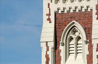
Keeping to the geometric theme of all my projects so far, i kept the similarity of the simple squares or rectangles. Replicating the building and using those graphs with 3 peaks, I thought about the castle balustrading and how it could almost ironically, being a castle and heavy, floating with these thin steel pipes being the structure underneath the heavy brick
After initial drawings, I decided to pay with scale models, to visualise 3D how the building would look, function and any other characteristics I did not think about.
I then followed the graph more accurately, looking at different widths and heights of the 3 peaks or rectangles on the stop. This I think, comes up with a stronger design than just 3 similar sized boxes. It also helps differentiate the building in plan and in elevations.
---------------------------------------------------
After initial drawings, I decided to pay with scale models, to visualise 3D how the building would look, function and any other characteristics I did not think about.
---------------------------------------------------
I then followed the graph more accurately, looking at different widths and heights of the 3 peaks or rectangles on the stop. This I think, comes up with a stronger design than just 3 similar sized boxes. It also helps differentiate the building in plan and in elevations.
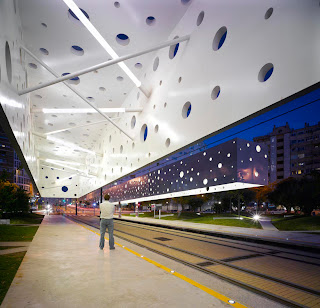
Exisiting Stops
Here are some tram and train stops that I found interesting, using steel piping they use simple geometric's to create I think amazing spaces and simple stops.
Busy Busy Busy...
Recently I have been contracted with a serious football team over the summer, Auckland City Football Club. Adding to the pressure, this will mean I am almost training everyday of the week, busy busy busy...
Pedestrian Traffic and Building Replication
After visiting the site and admiring the High Court building, I wanted to somehow replicate the original building, as its a Architectural History tram tour, so I wanted the stop to somehow replicate the building as if part of the tour or route. Thus I came up with materials being brick, and steel piping as it was our task to use a material from our last project 1:1 model.
Also, after being on site, I noted there is a lot of foot traffic through and around the site, as it is a main route for students from the university. Thus I decided to go to the site at different hours of the day and note the frequency of pedestrians, after visiting the site 5 times that day I filled in the rest as an assumption and graphed my results.
After graphing these results, I decided to use the frequency of pedestrians, or shape of graph be the initial shape of my stop, being 3 dominant features and low lying areas, might be interesting to use this and see how space and voids are created.
'Gifting' Site Analysis
After being given our breif, my task was then to get a good understanding of the surroundings of the route, especially the stop and building I hope to design the building for. In this case, the High court was just down the road from the Architecture buidling. I mapped all the useful information on this page, indicating wind, light, shadows, pedestrian traffic, vehicle traffic, other public transport routes etc. This was greatly helpful as after talking to the tutors, they offered advice that I should picture myself in this stop and asked 'What do I want?'. This was agai useful as I thought wind, seating, lighting etc. Sorry for the picture quality... as i have seemed to have lost original file.
Week 8&9: 'Gifting'
After again changing tutors, our task for this 2week project was to gift the city of Auckland with a Tram route which included 12 tram stops, one in which he had to design within our set area. In groups of 4 we decided on the basis in which our tram route would run, eventually deciding on an Architectural History tour around the CBD of Auckland. I decided to pick a tram stop sitting outside the High Court, as I thought it was an interesting site, including a very busy traffic, pedestrian route and included a park, with a large gradient.
The route of our tram, starting on the Viaduct, Wynyard Qtr and looping around 12 stops or historical buildings.
Sunday, 2 October 2011
1:1 Model Detail
For my final 1:1 model, I decided to focus on the structure of the spiral and how it connects and joins to the floor of the office. I decided to go with steel piping as it is very strong and is able to bend, thus creating a spiral. The steel piping spiral is in a latticework formation that will provide strength as a singular spiral will not be structurally sound.
The detail contains two steel pipes either side of the main structural beam, this helps support the building and floor. The steel lattice also goes through the floor extending to the roof, which I think adds an effect when inside the office as you can see the structural latticework. The angle of the pipes indicate the top of the spiral, as it extends through the floor, each spiral, 5 in total is bolted to a beam in this manner.
The detail contains two steel pipes either side of the main structural beam, this helps support the building and floor. The steel lattice also goes through the floor extending to the roof, which I think adds an effect when inside the office as you can see the structural latticework. The angle of the pipes indicate the top of the spiral, as it extends through the floor, each spiral, 5 in total is bolted to a beam in this manner.
Model work 1:5
After talking to Dermit and Padma, and presenting my drawings, they seemed to like the idea of the natural looking supports of the Toyo Ito building and the spiral structural scheme I drew at my site. Due to this I modelled a interesting way that incorporated the spiral scheme, this structural support lifted the building or office of the ground to produce the office to be lifted significantly of the ground. While there is a sense of floating of the building, I wanted to illustrate the strength and scale of the structure so produced large columns that were supported by the spiral, while still trying to incorporate Toyo Ito's idea of a natural support.
As I developed this model further I realised that the spiral became more of a decoration than a main structural aspect, on the 1:1 model I should further develop and focus more on the spiral, exaggerating it.
Doodling...
As I developed this model further I realised that the spiral became more of a decoration than a main structural aspect, on the 1:1 model I should further develop and focus more on the spiral, exaggerating it.
Gathering continued
After producing three augmented drawings that related to our matrix building, we were asked to then personalize a site with a few ideas that included our original starting points. My starting points were Regan's ideas of isolation and the sense of a spiral, I also include ideas from my matrix building that I pulled out in my earlier drawings. The task was to design an office that included the views of 5other people or 'friends', thus needed a function to the office. These drawings were initial sites, and initial idea work that developed from my starting points.
Wednesday, 24 August 2011
Week 6&7: 'Gathering'
Augmented Drawings was week 6's tasks, producing firstly 3 augmented drawings of our precedent buildings (given matrix). Our task was to come up with ideas from the building we were studying and draw abstract or simple drawings that mould with the picture to create a somewhat 'augumented reality'. I came to the conclusion on the Sendai Mediatheque building, produced by Toyo Ito, that the main structural elements were based or schemed of natural supports (e.g Trees). From this I produced work that showed how trees could support or grow from the building.
The last image, instead of showing a meaning behind the drawing, I decided to show the structural aspects within the building and the joints of different materials that exist. What i find interesting about this drawing is the amount of layering of different materials that he has used.
Subscribe to:
Comments (Atom)


